#003 E-Miata
last updated: 9/16/23
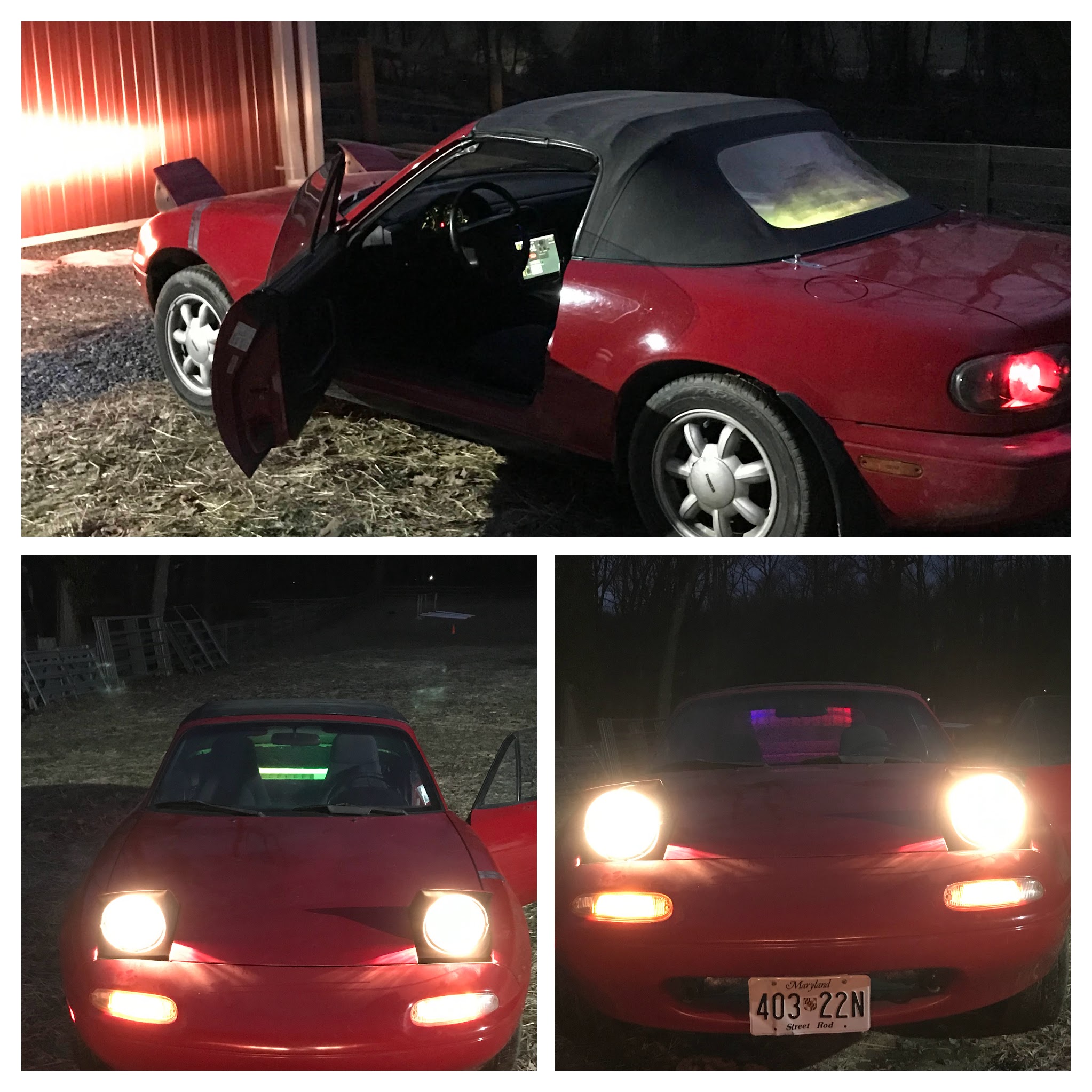
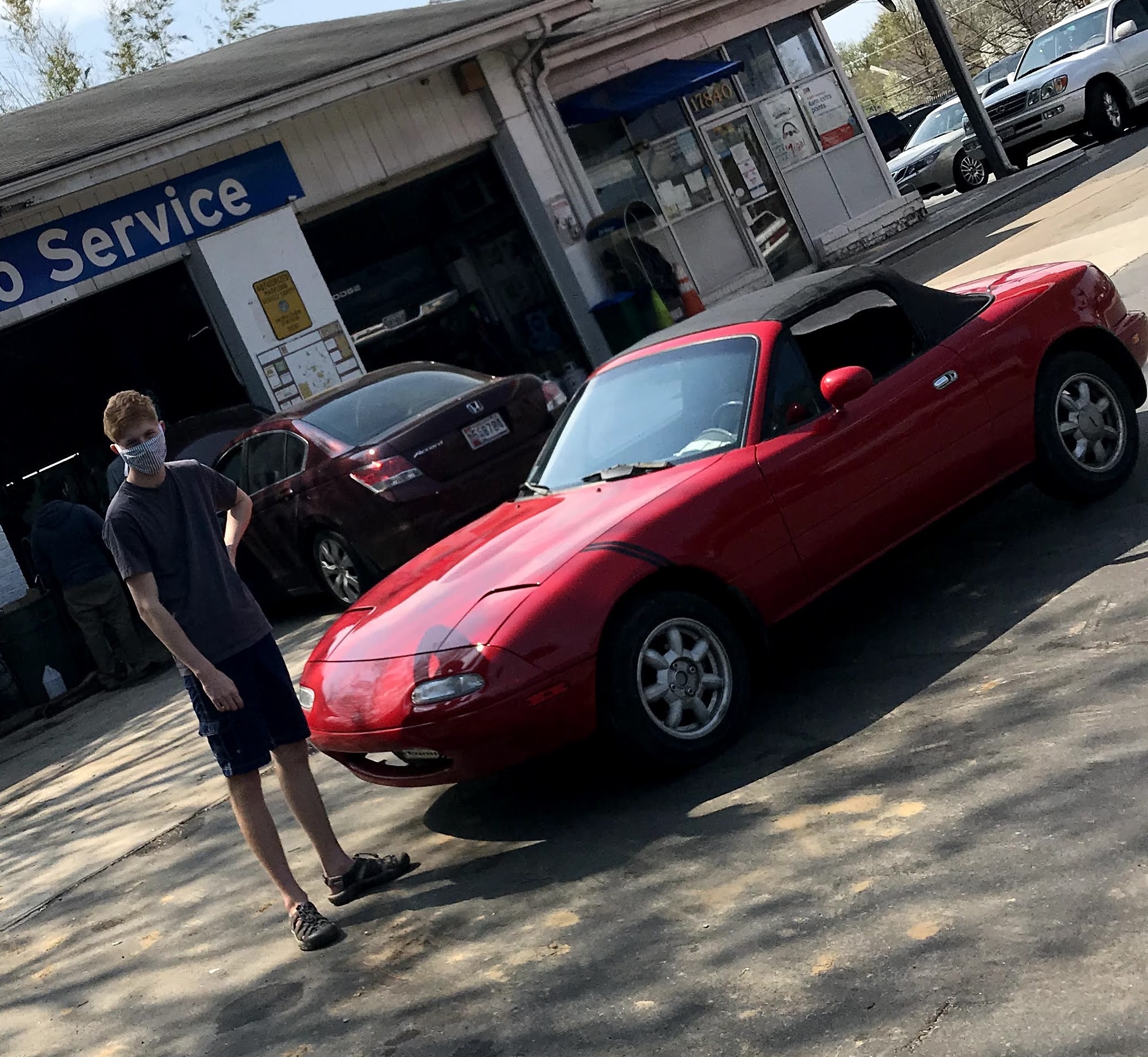
Over quarantine, (~9/20 to ~8-21) I worked on converting a 1990 Mazda Miata to run using an electric drivetrain.
I bought a body, mounted electric motors, assembled and mounted a battery pack, and ran wires. It is was
fully electric and can be plugged in using public charging.
However, the original design on two motors connected via a chain to the transmission was very noisy and wasn't torque-y or smooth. Over winter break of my sophomore year of college, I did a sprint to replace my two motors with a single Warp 9 motor that was directly connected to the driveshaft without the transmission.
Summer of 2023 I finally built up enough courage to take the car some distance - I decided to drive it on the highway and up the mountains to my summer camp job. (50 miles). At the top of the ~1000 ft hill climb my front battery pack caught fire. The fire was slow and I was was never in danger, but the car was not salvageable. This sadly devastatingly concluded the project. I learned a lot and grew immensely over the time that I worked on and drove the car, and I don't regret anything, besides being a little more cautious about testing a new battery pack.
I have not updated the tense of the article below.
Overview
- LIGHT! Lighter cars get better performance from cheap electronics than a heavier car would.
- Mechanically and electrically SIMPLE. (Manual transmission and minimal (or at least lenient) engine diagnostics)
- Be CHEAP! Cars made after 2000 aren't worthless yet; before 1980 has historical value.
Batteries
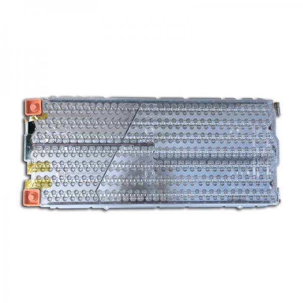
Originally, the plan was to use 3 Tesla Modules (see right) getting about 12 kWh (18s) and for about $3600. Once I started digging, I got the notion the DIY option (spot welding cylindrical cells) could be 1 to 2 thousand dollars cheaper, in addition to being able to supply the exact voltage and capacity I wanted. I started research by looking at 18650 cells, finding a few cheap options. However, a few folks over on the DIY Energy Pack Discord pointed me toward a somewhat more reputable company, where I found an even more cost efficient battery.
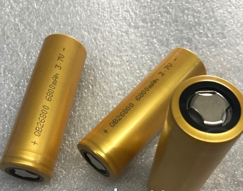
Not only was the QB26800 battery (see far right) cheaper (including shipping from CN) than the Tesla cells, the bigger form factor would require less welding connections to assemble the pack compared to a custom 18650 pack. (by a factor of about 2.5:1). It would also supply more current due to the 5C (5C * 6.8 Ah = 34 Amps per cell * 40 cells = 1360A, on the half pack that's 680A) max discharge rate.
Should I have built my own battery pack? No. But I learned a lot doing it - I even built a pack for my bike out of leftover cells.
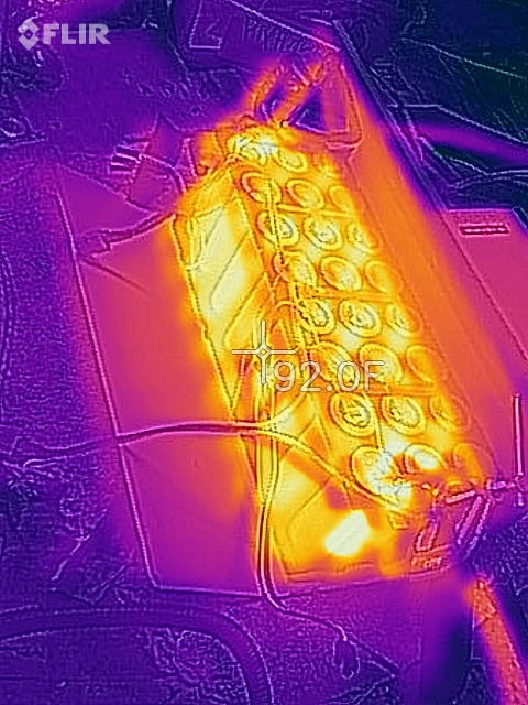
Testing the QB28600 Battery
Quantify Heat Generation
Determine Cell Quality
Battery Monitoring
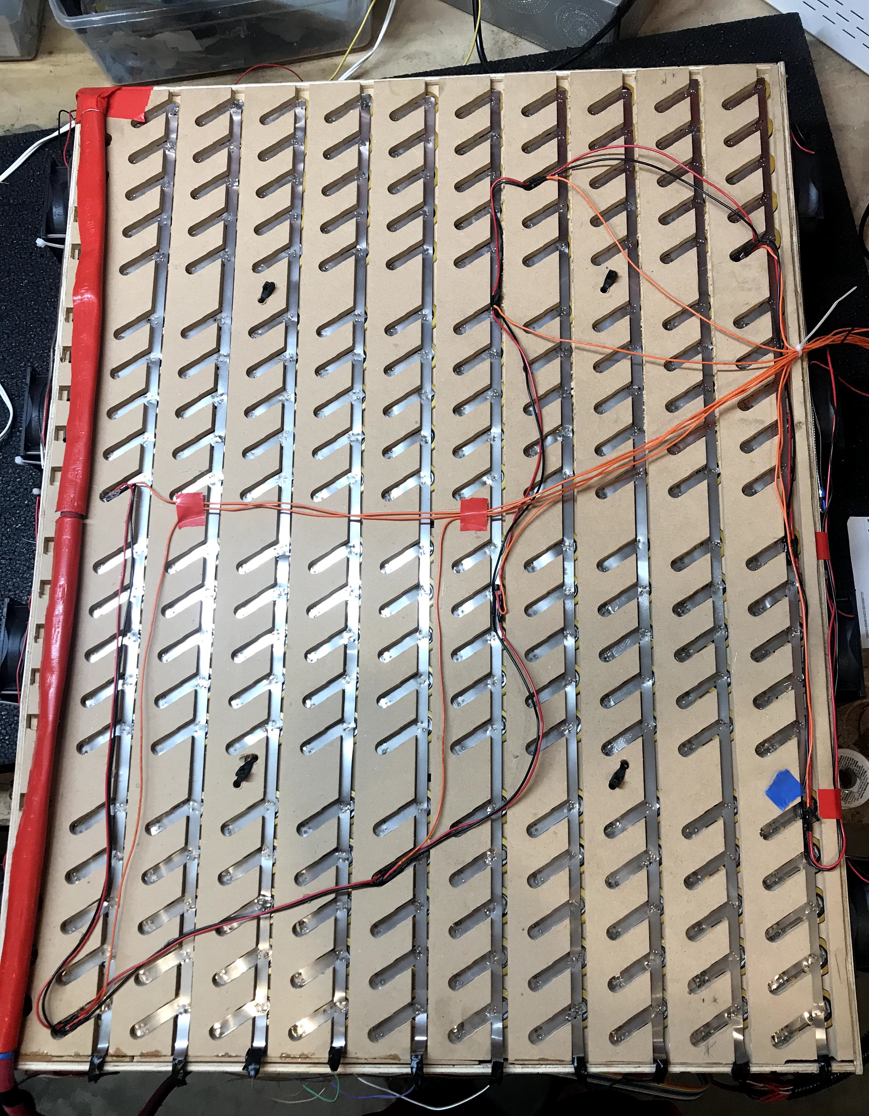
Design
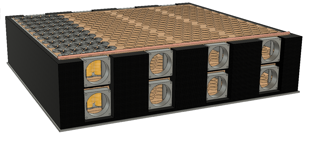
Physical Construction
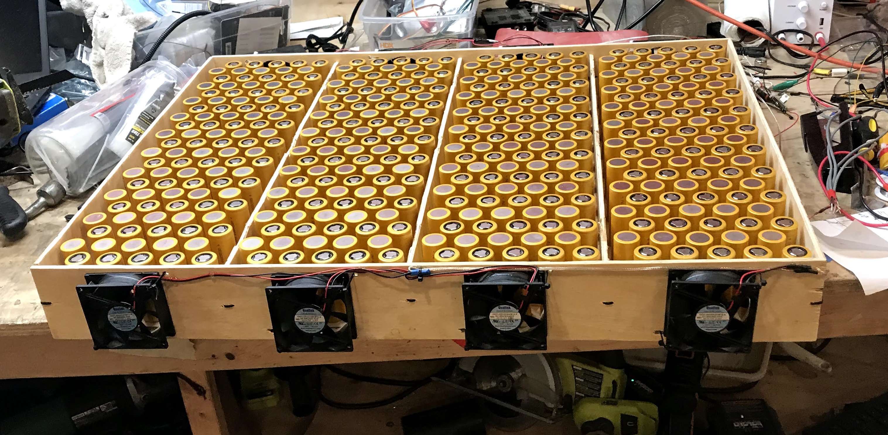
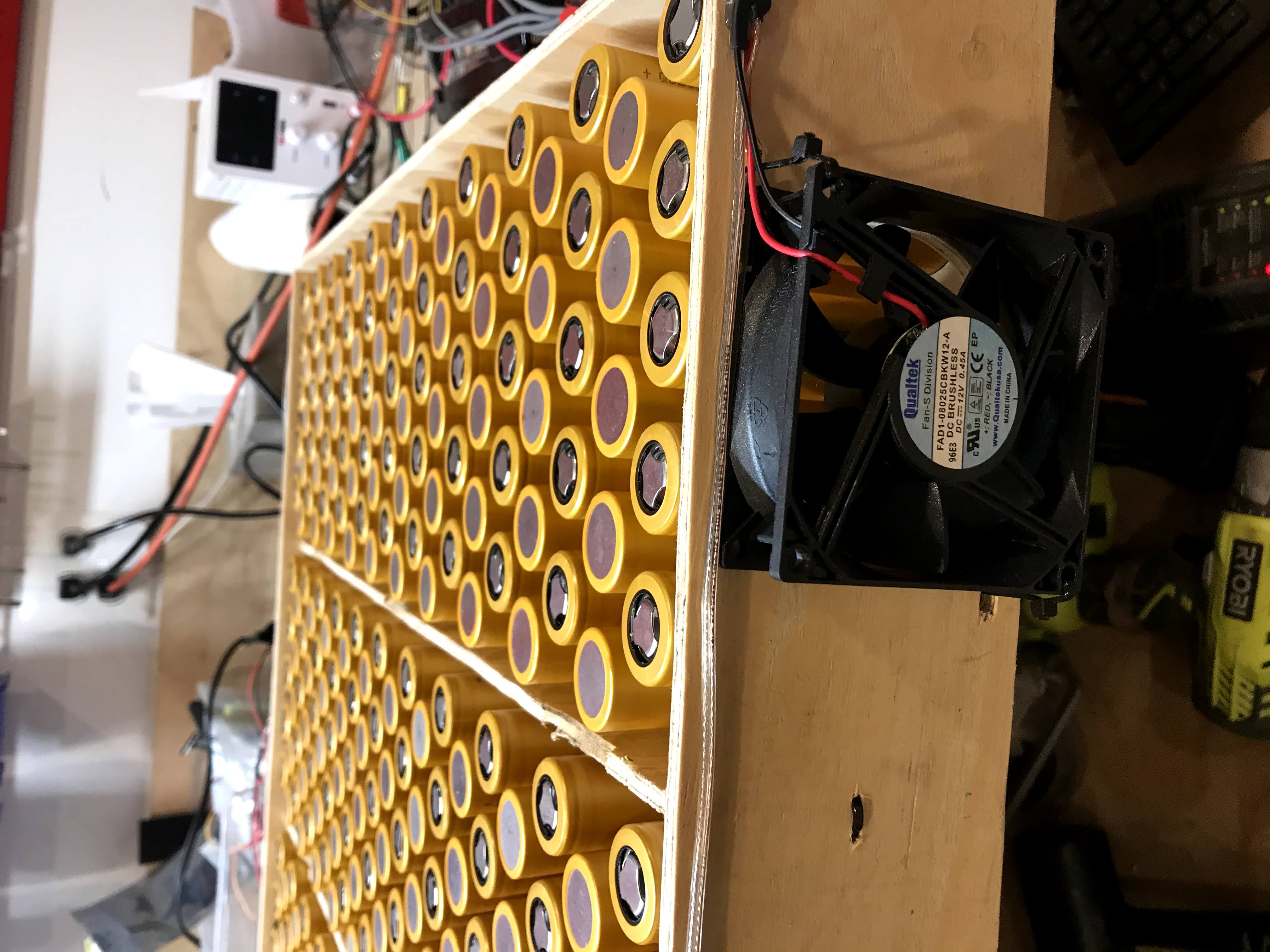
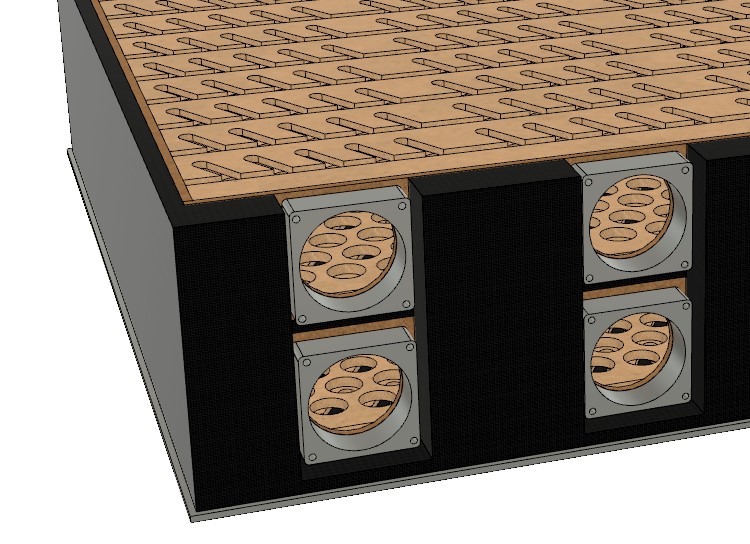
Temperature Management Solution
V1 Motor Setup
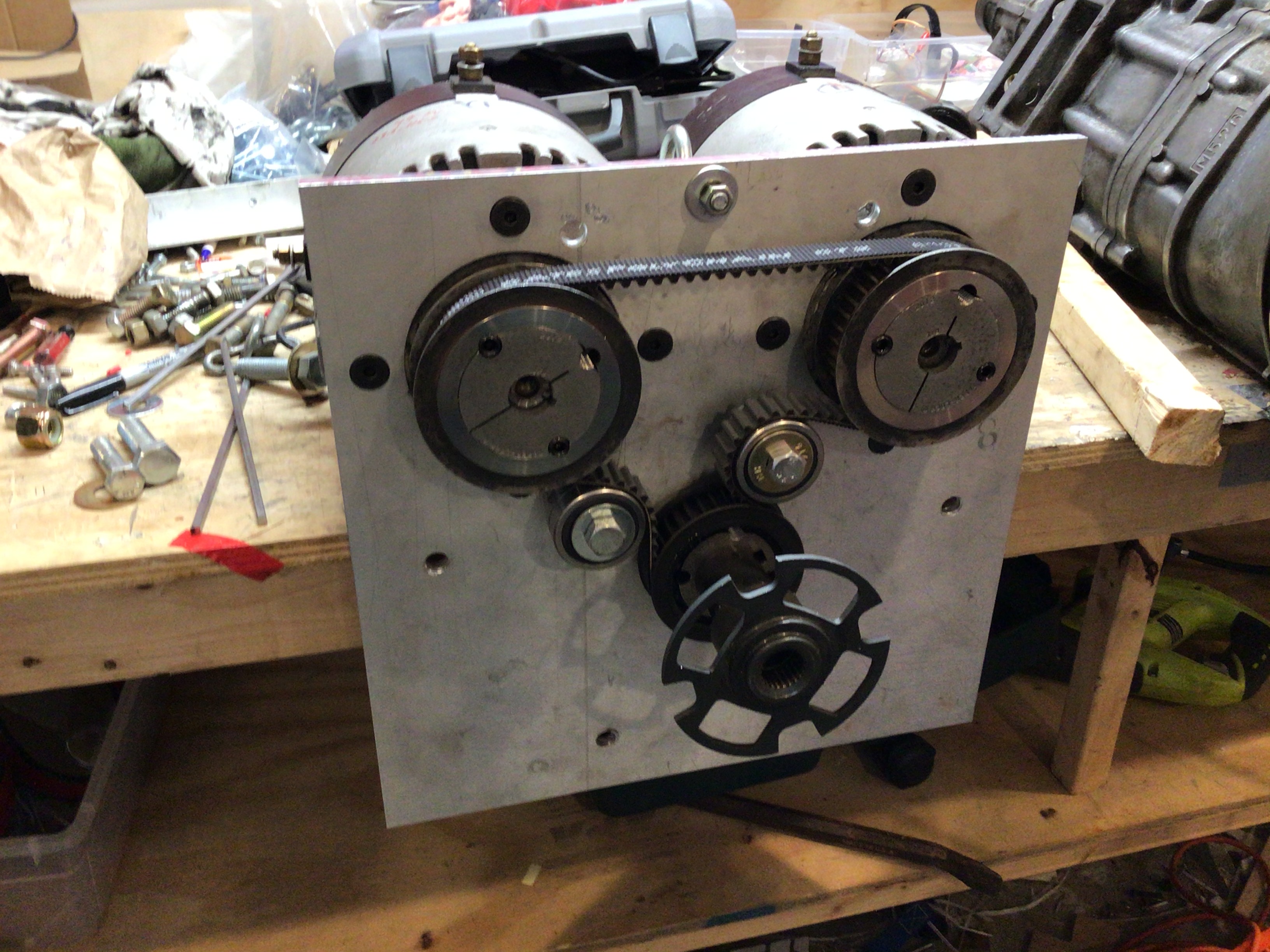
I used two ME1007 motors for the original motor setup. They are bolted onto a 1/2" aluminum plate that then bolts to the transmission housing.
However, 3.7 miles into the first road test, the belt snapped. I had to decide between a chain drive, a wider belt, and gears. Gears would mean enclosing the space, and potentially moving the motors. Expensive and time consuming. Widening the belt could be hundreds of dollars for each wider pulley. New sprockets and chain would set us back 70 or 80 dollars, far cheaper than the belt upgrade. I made the switch in a day and had the car driving. At the time of writing, V1 has traveled over 100 miles on the chain drive. The noise is higher than the belt but only slightly so. I am very pleased with my decision.
One question I get a lot is about the transmission. The manual transmission has remained in the car for version 1 for two reasons: it is fun, and it spans three of the six feet from the motors to the differential. Yes, i just keep it in 3rd the whole time.
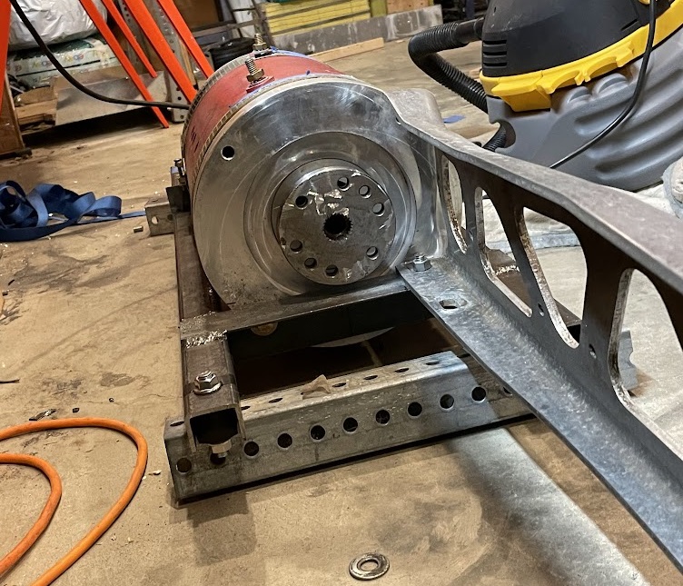
V2 Motor Setup
The last setup was noisy, was not conducive to acceleration, and the chain slipped under high torque. Pretty bad.
So, here's version 2.
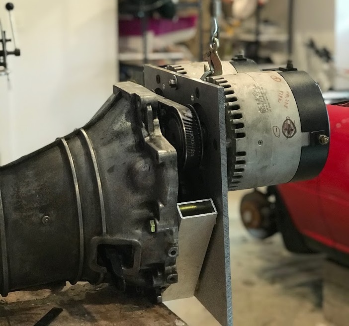
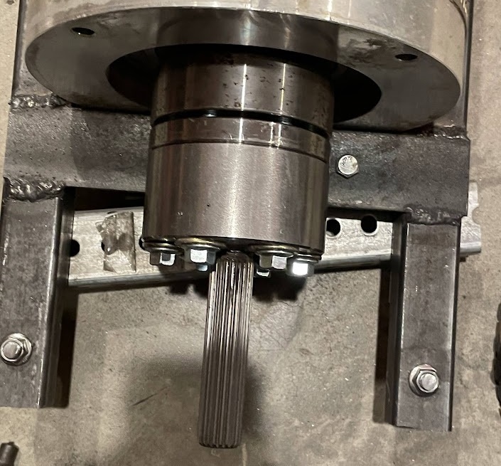
The Sled

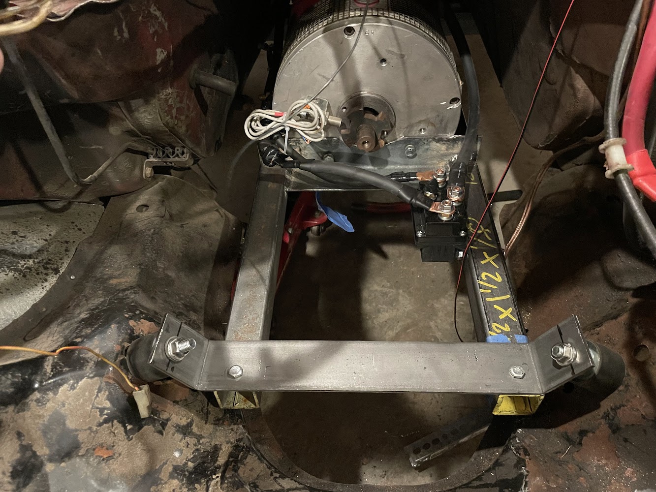
The motor sits on a welded metal frame. I designed the frame in Fusion 360, bought the metal at metals supermarkets in Beltsville, cut it at home with an angle grinder and had it welded by a neighbor. For my first ever steel welded part, it came out pretty well. I coated it with a rubberized top coat.
The frame is directly bolted to the power plant frame that is attached to the differential. The reaction torque force from the differential pushes it forward (wheels pushing backward, diff rotates around rubber connection point and pushes itself forward). Something must resist that force - in the original car the Power Plant Frame (PPF) was attached to the transmission which connected to the engine. The forward force was absorbed by the engine mounts.
In my design, the forward force goes into the PPF. The PPF is bolted solidly to the sled. The sled is mounted on rubber mounts, so the PPF can still move - like it did when connected to the engine.
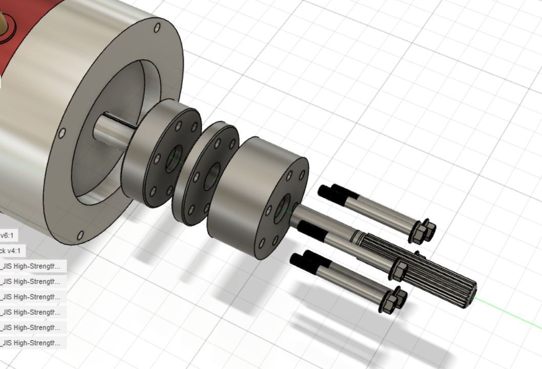
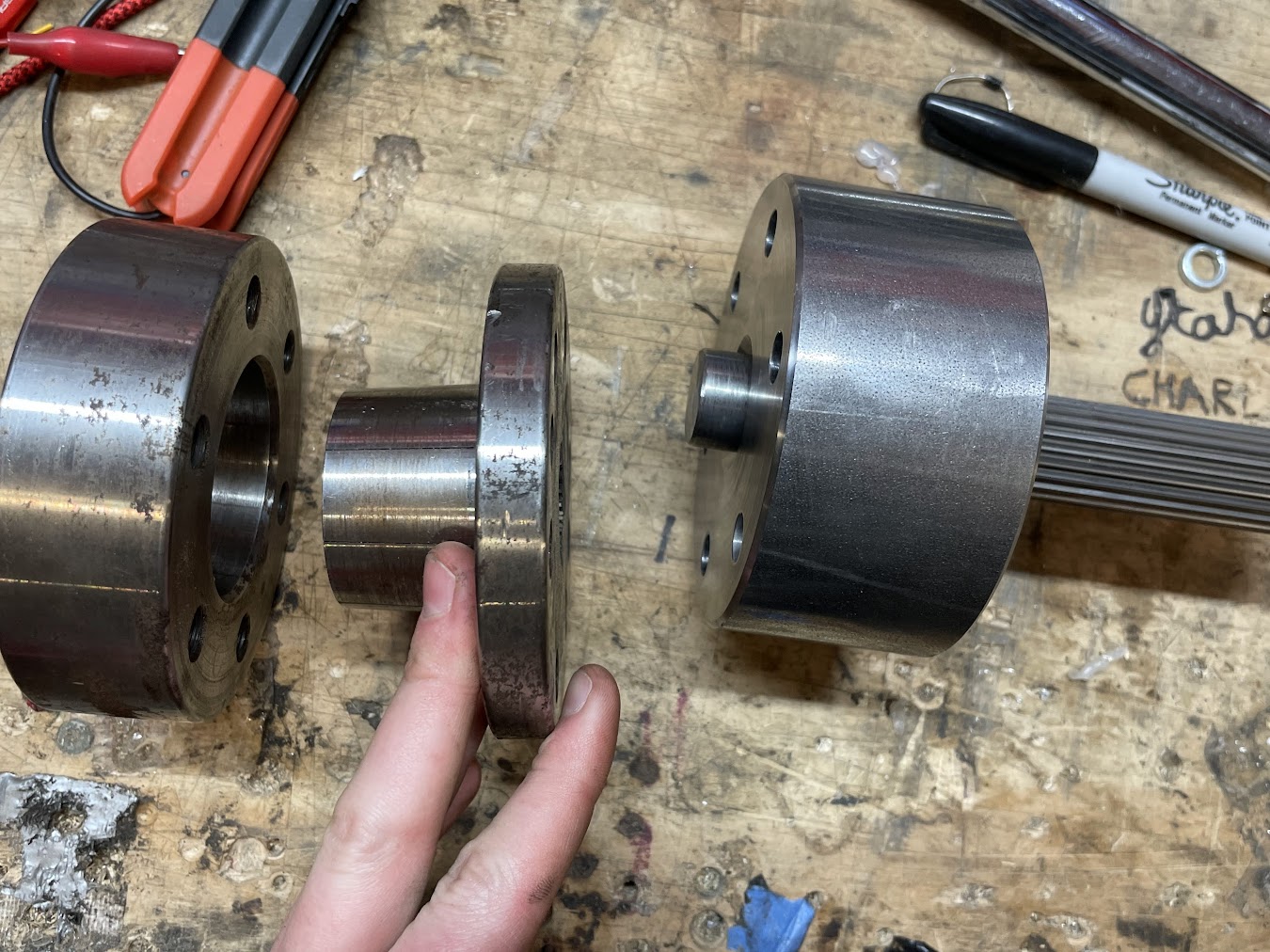
The Adapter
The adapter changed the most over the course of the design. I was set on having the adapter attach to the motor shaft via taper lock bushing. Luckily, the motor came with a taper lock and taper lock hub. I decided to machine a circular block with the correct bolt holes and center hole to weld a section of the old transmission output shaft into it. My machinist made sure that the hole for the shaft was perfectly straight relative to the holes for the bolts, so I knew the spline shaft would be dead straight. Sure enough, it is!
Motor Controller
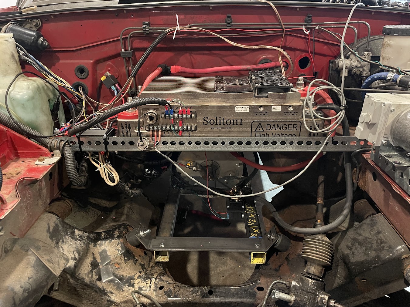
V2
V2 uses a Soliton 1 controller. 340V max, 1000A. A beast. Super smooth, cool user interface. Pretty sure the company that built it fell apart so I am toast if it breaks... otherwise not much to say.
V1
V1 used a Alltrax 7245 DC motor controller. Although this model is outdated (as are the motors), it provides 450 amps at 72 volts which was enough power for V1. The controller is controlled by a 0-5k potentiometer pedal and enabled by the key ignition. Not comparable to a Tesla (Model S base model has 285 kW (382 hp)), but as of the V2 battery the car reaches 65mph and can take most hills at 45 mph.
Vacuum Brakes
V2 (EZ version)
For the v2 car I replaced all of these parts with a more professional pump, reservoir, and switch that was thrown in along with my Soliton 1 purchase.
V1 Car (DIY Version)
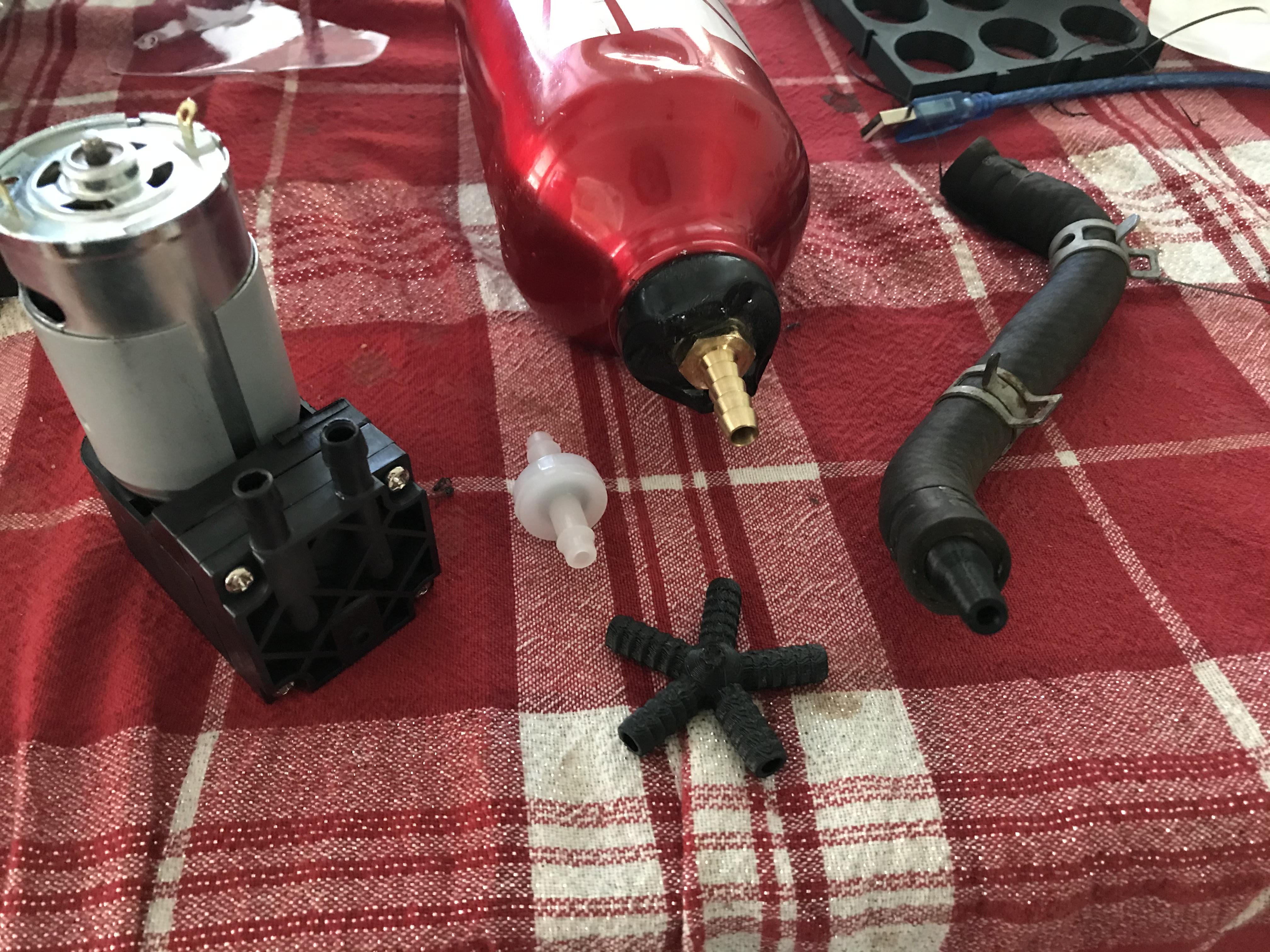
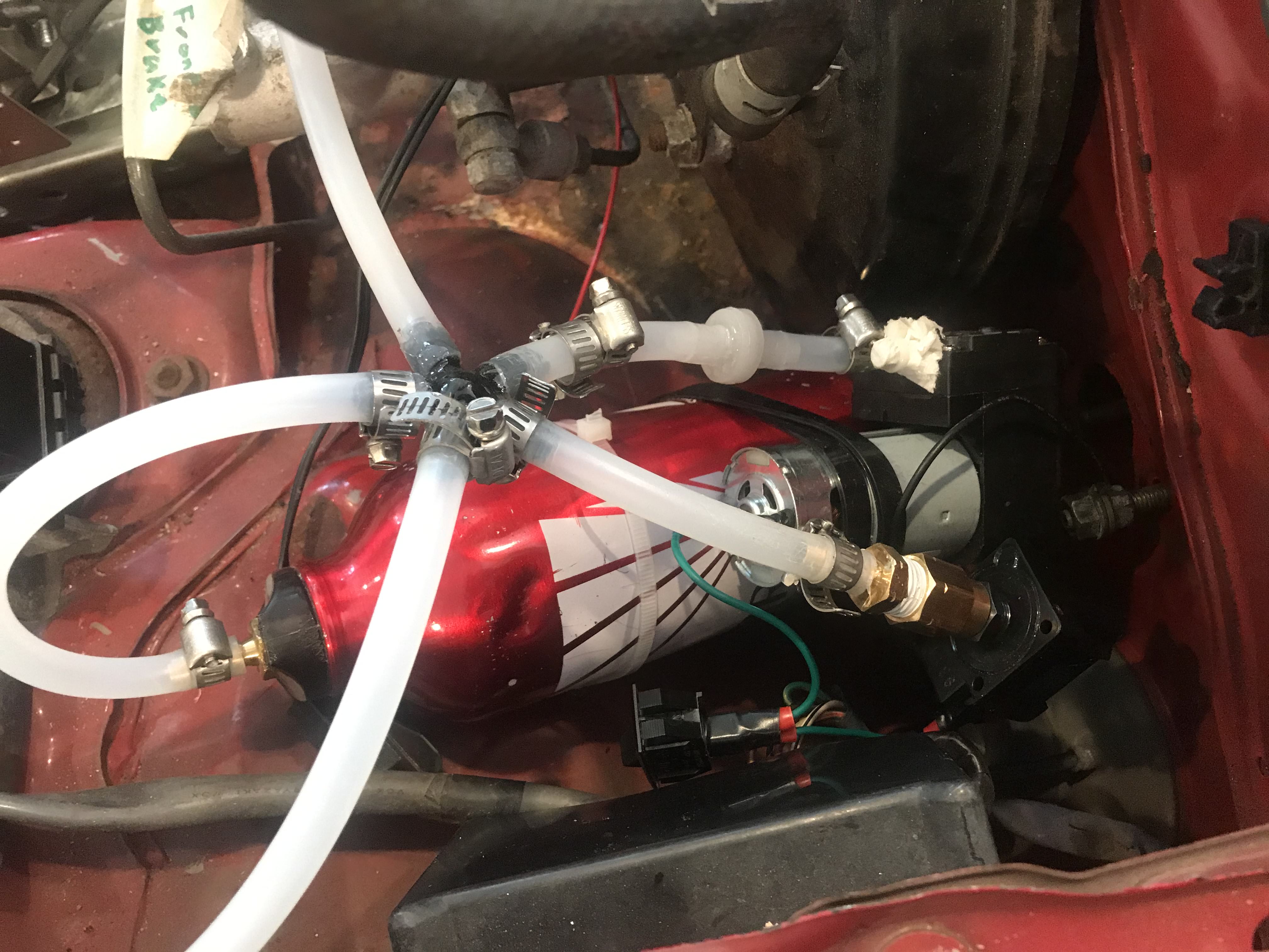
There are several components that run off the engine power including the power steering, air conditioning, power (vacuum) brakes, and heating. The latter two I decided to implement. Vacuum brakes on gas cars usually use the air rushing into the throttle, employing Bernoulli's principle to deliver a vacuum and assist the master cylinder. Sadly, we have no engine.
The vacuum system consists of three main components: A vacuum pump, a vacuum buffer(empty can), and a pressure switch to actuate the pump based on pressure levels. I bought a 12 volt vacuum pump from Amazon, made the buffer with a brass fitting and an old aluminum bottle, and bought the switch. During this time, I learned that I could 3D print airtight parts, so I printed a 5 way tee and the adapter to the hose that attaches to the brake booster out of ABS and reinforced it with epoxy.
The brakes switch when the ignition switch is in the run position. It is not very noisy compared to the noise of the engine. When stopped it is the only source of noise and noticeable when the speakers aren't on.
After a year the parts were quite leaky... So they got replaced.
J1772 Public Charging Socket
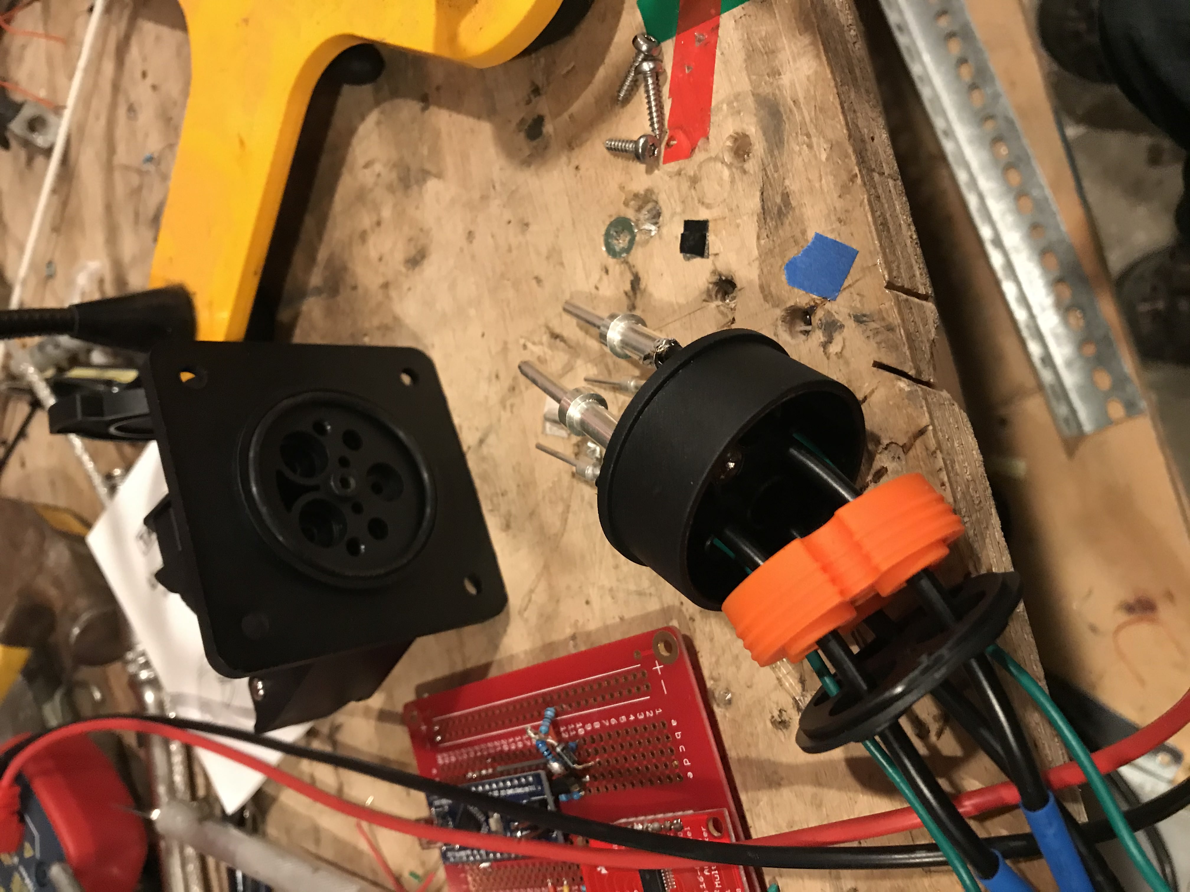
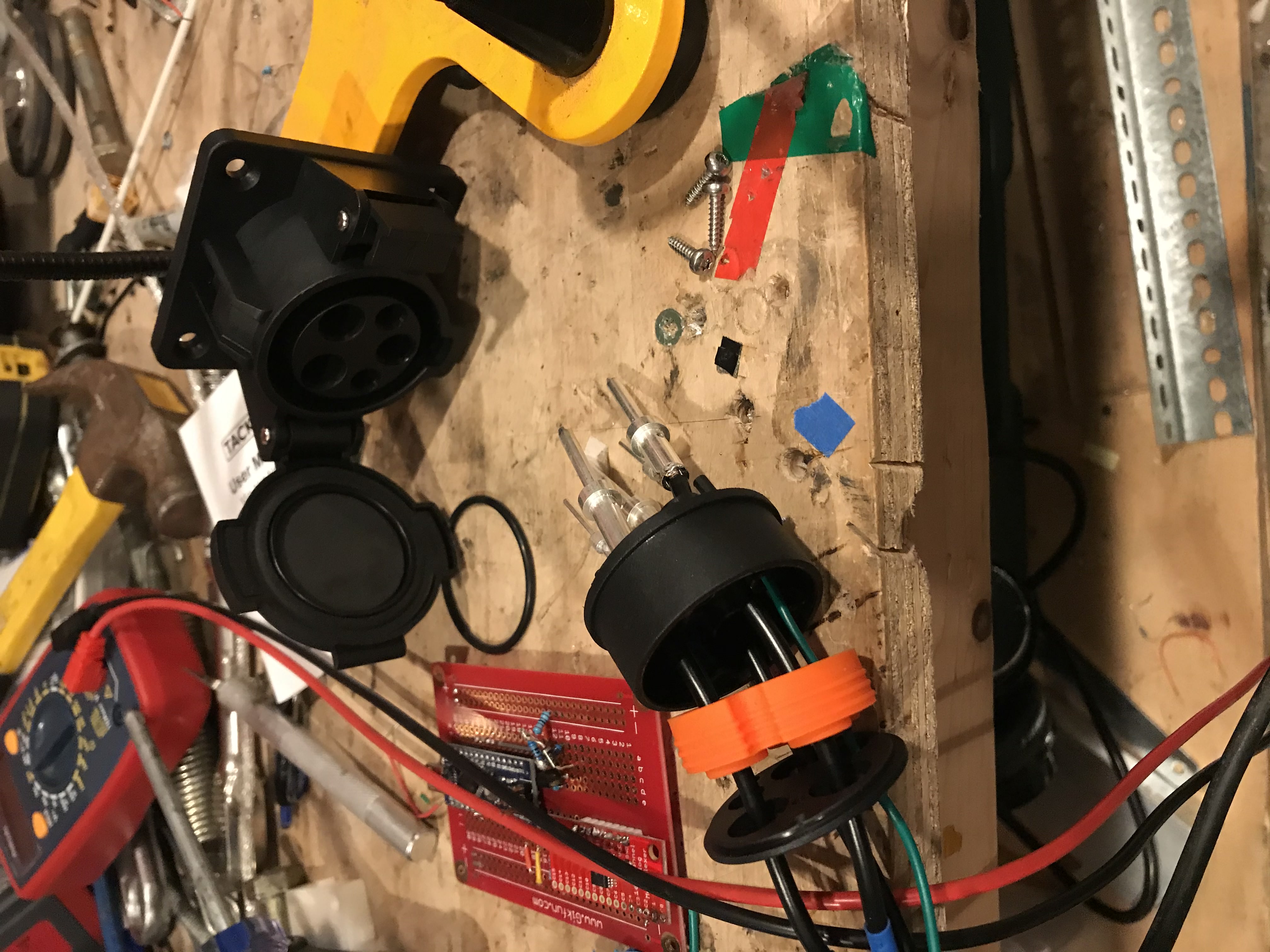
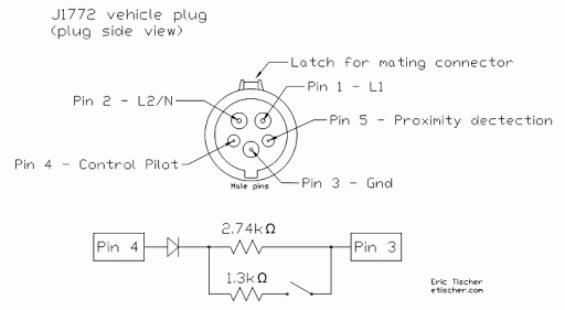
The J1772 was one of my favorite parts to build.
Accessories
Onboard Screen
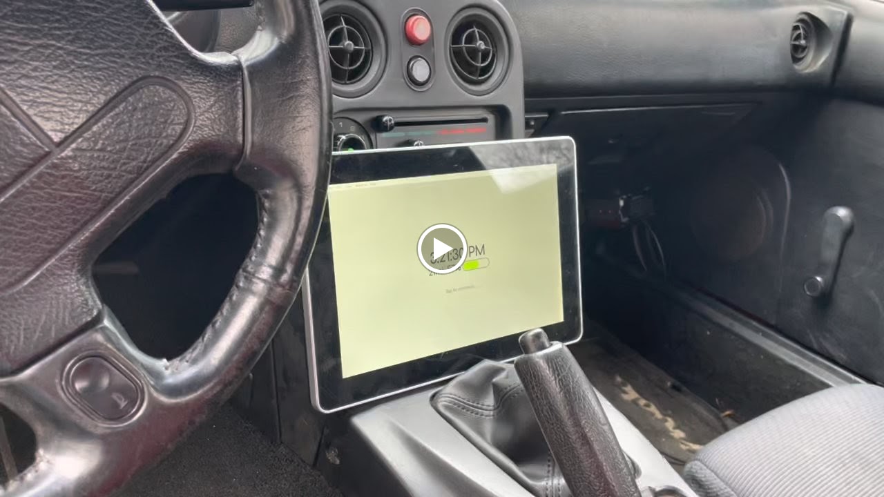
Available information includes
- individual cell voltages
- balance status
- voltage statistics
- a graph of the voltage over user specified duration time
- Battery and motor current as reported by the controller
I build the Electron app on my laptop and then use a script to upload it to an Amazon bucket. The bucket is downloaded and ran manually. You can see the code for this app here.
Inverter
Charger
Performance Specs
| Characteristic | V1 (Aug 21 - Dec 22) | V2 (Jan 22 - Jun 23) | V2 (Jun 23 - Fire) |
|---|---|---|---|
| Max Speed | 65 | 53 | 80+ |
| System Voltage | 88.2V - 74.2V (21s) | 88.2V - 74.2V (21s) | 172.2V - 144V (41s) |
| Actual Power Throughput | ~10 kW | ~30 kW | ~80 kW |
| Battery kWh | 10.5kWh | 10.5kWh | 21kWh |
| Max range (mi) | 35 | 35 | 70 |
| Time to full charge | Level 1: 8 hours, Level 2: 2.5 hours | Level 1: 8 hours, Level 2: 2.5 hours | Level 1: 16 hours, Level 2: 2.5 hours |
| Acceleration | 💩 | fun | really fun |
| Flamability | low | low | high |
Future Plans
Upgrade the speed controller to a 144 volt 1000 amp model. (One that supports 72 volts as well)(Jan 2023) - Got Soliton 1 controller: 340V 1000VUpgrade the drivetrain to a single 144V 1000A motor directly powering the wheels.(Jan 2023)Upgrade the batteries from a 21s to a 40s or 60s (more likely) (3.7V*40=148) or (3.7V*40=222)- Switch the electronics over to CAN Bus using a custom PCB CAN node.
This results in a 150kW setup, direct drive. That is a significant upgrade in power (and noise, the chain was quite loud) to the current V2 setup. Performing the steps in this order allows the car to be operational in between all of the steps.
As of January 2023, the motor and controller upgrades are complete and the car drives great up till 45 mph. The additional voltage will help lower battery currents and allow for continued acceleration to a higher speed.