- Voltage Dividers - the board could read an 8 cell Li-Po/Li-ion battery - so up to 4.2*8 = 33.6V. Simple resistor voltage dividers dropped the voltage for the ADC.
- Multiplexer - an 8 channel analog multiplexer (CD4051BE) was used to switch between cell lines.
- Analog to digital converter - A 12 bit ADC (ADS1000A0IDBVT) was used to read the multiplexed signal.
- MOSFETs - each cell has a 2.8A 20V MOSFET (DMG2302UK-7) to switch the balance current used to remove energy from the cell.
- MOSFET Isolators - two isolator modules (LTV-846) were used to switch the MOSFET gate lines. The isolators would pull the gate high (to the positive of the cell) or low (to the negative of the connected cell).
#007 Battery Mgmt. PCB
last updated: 9/6/23
I designed, build, and tested a PCB that measured and removed energy from lithium ion cells in parallel. This functionality is typically labeled as BMS or battery management system - although usually a BMS will have additional components that allow the battery to be disconnected when the voltage/current is out of a safe range. My 'BMS' was intended to be connected when charging and would remove energy from cells via balance resistors when the cells exceeded a certain voltage.
Design
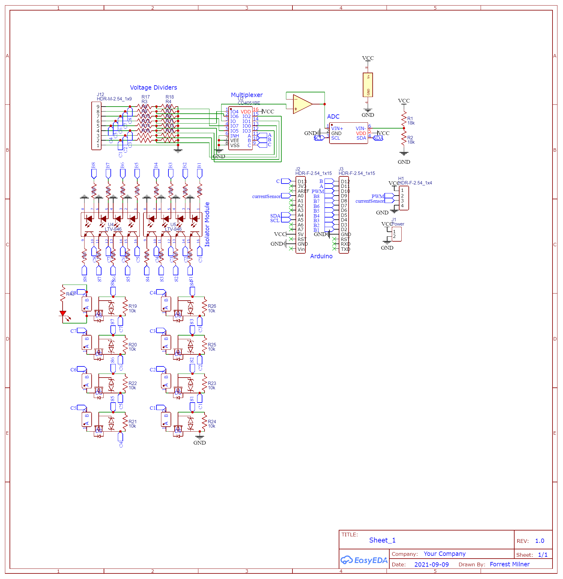
Schematic for design. Mostly labelled. I left breakouts to connect a possible charging circuit.
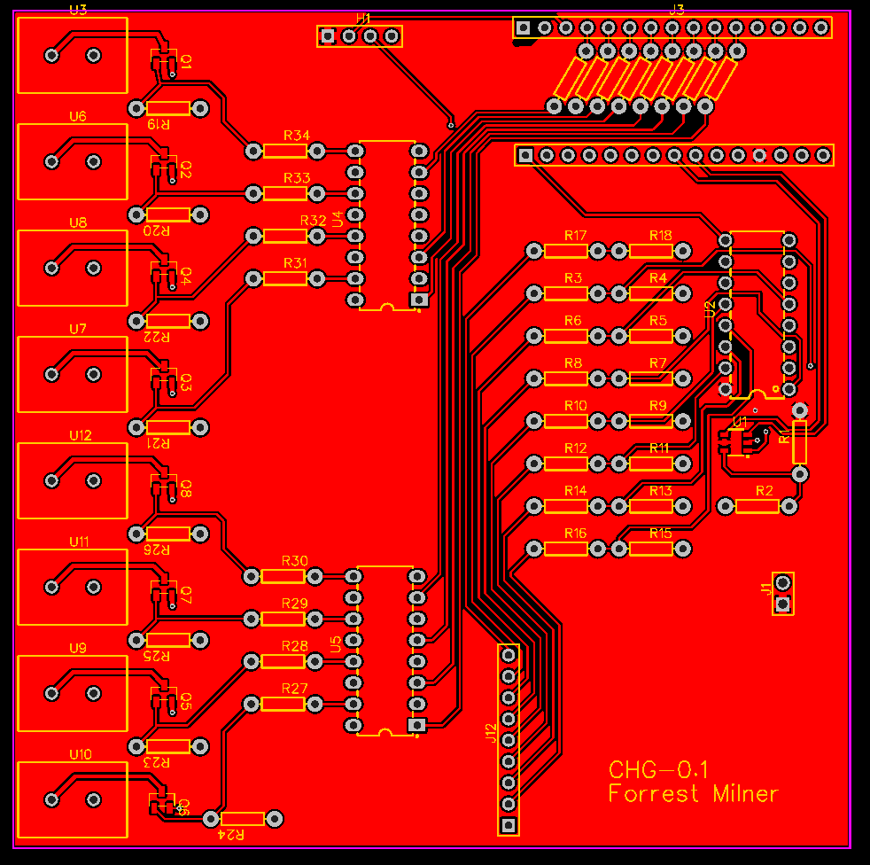
PCB for design. Anything over 100mm by 100mm cost more, and since I wasn't interested in handling space constraints, the boards are 99mm by 99mm.
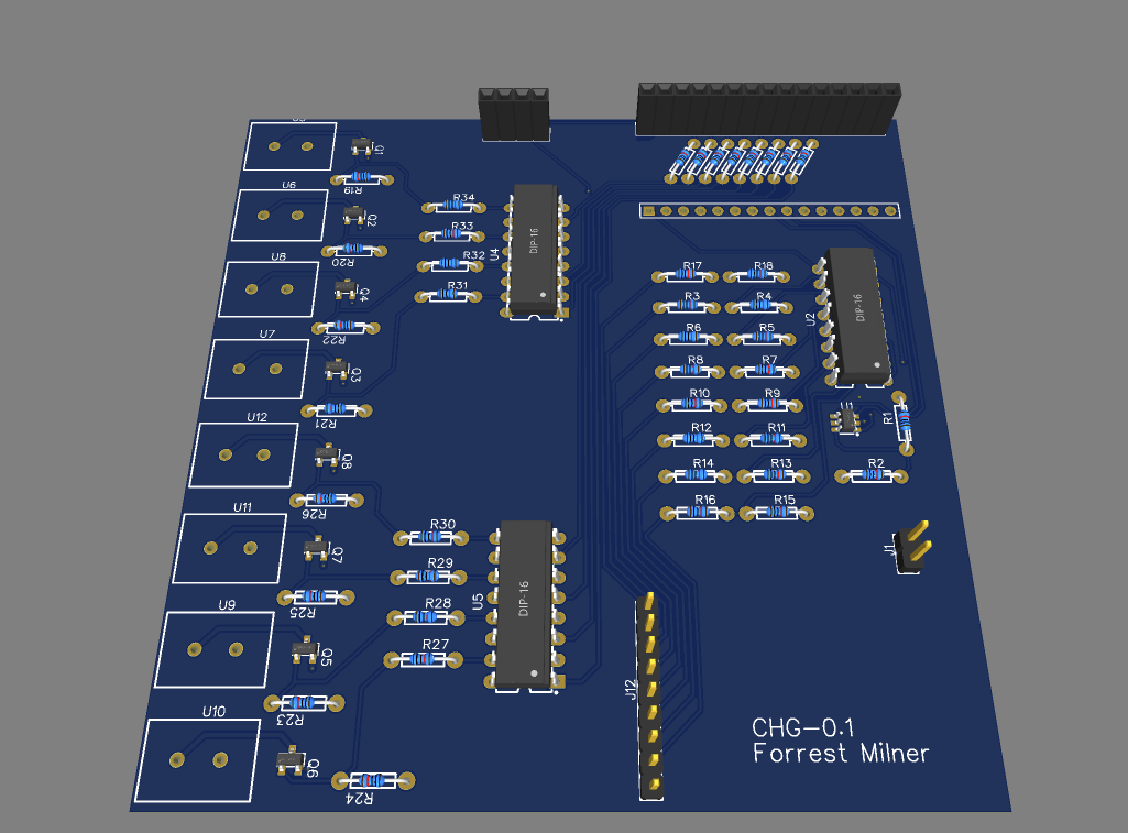
Rendering of populated board.
I used EasyEDA to create the schematic and pcb. It is free and easy to learn. I am sure a more professional technology would have created a better product - but it worked so who can complain. Plus, you get a coupon on your first order of the month on JLC PCB that makes the order for 5 boards (including shipping) only two dollars, so basically free.
The board consists of the following parts:
Construction
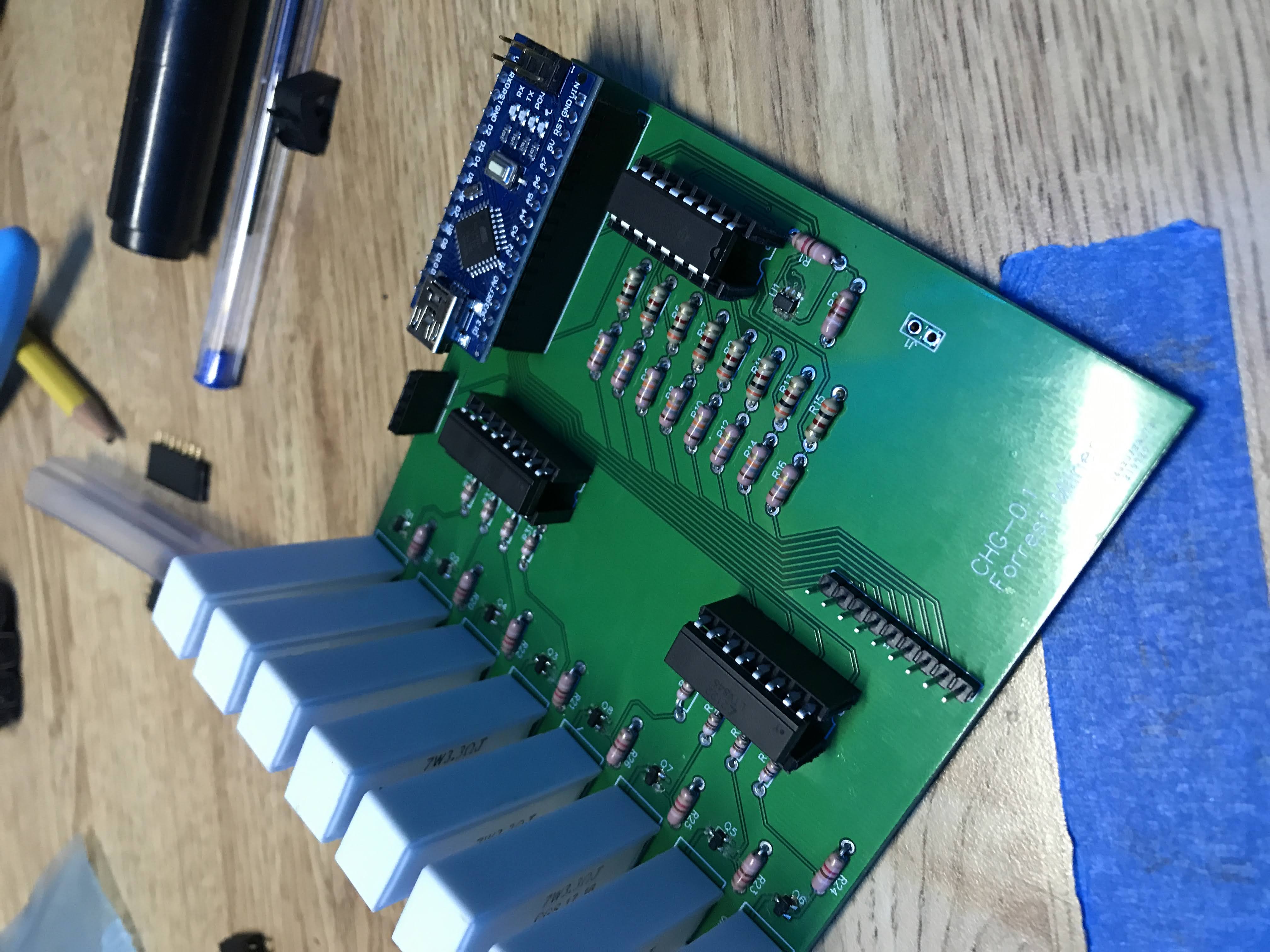
Populated board.
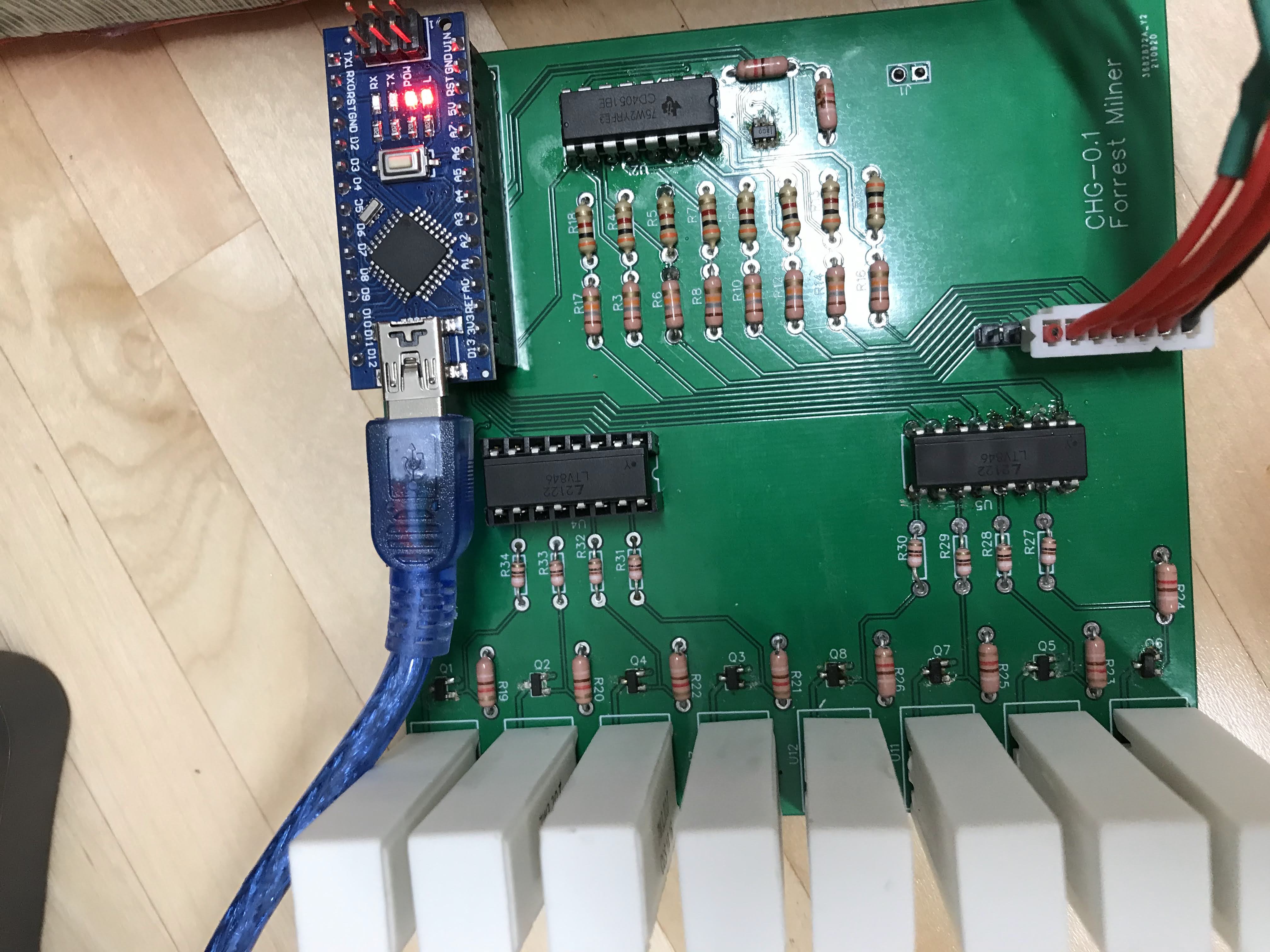
All components were through hole except for the MOSFETs. Since there were only 8, I used a soldering iron and a little bit of patience and got them all down. Everything else was easy through hole components.
Testing
The board features a spot for an Arduino Nano to be dropped in. I honestly think that dropping an MCU in with headers like that is the way to go - it saves the hassle of complementary components for the MCU and breaking pins out - plus if you burn one it is super easy to pull out as opposed to a soldered down surface mount component. Footprint wise it is not a win, but that wasn't one of my constraints / goals.
I coded up the Arduino - I luckily made all connections correctly the first time on the PCB. It was scary to power up the board of course, even more so to plug in a battery. However, I was up and running with a calibration script pretty quickly.
Results
Using a voltage divider to read a 30 volt signal isn't a problem - but when you are looking to subtract away 26 volts, it isn't so precise. I used cheapo resistors that I am sure fluctuated with temperature. It was precise maybe to 10 mV once calibrated, but the calibration didn't last long. So that aspect was usable but not great.
The biggest problem was that when one amp was drawn (That's how much the resistors drew) the voltage dropped so significantly that the resistor then turned off. I don't think I really ever got it out of this fluctuating behavior without turning off the resistors to read the cell values. I wrote the software so it would turn off the resistors, wait a second, measure, and then turn on the resistors for the next 10 seconds based on that state. This was an advantage of using a MCU instead of op-amps with fixed cutoff values.
The voltages would be printed out on the Arduino serial monitor, so I could watch the cell values while charging.
Go To Top Guess what? I made this website! Check it and many of my other projects on my github.